Industrial automations
From the precise control of pumps and fans to complex systems for power plants and medium voltage applications, our services are tailored to your unique requirements
At ITI Electra, we deliver robust and reliable industrial automation solutions engineered to optimize your operations. Our extensive experience spans a wide spectrum of applications, from the precise control of pumps and fans to sophisticated systems for critical infrastructure like hydroelectric and thermal power plants.
We are experts in implementing advanced motor protection systems and have proven capabilities in designing and deploying complex medium voltage applications. Our goal is to provide intelligent control systems that enhance efficiency, ensure long-term reliability, and safeguard your valuable industrial equipment. Partner with us to implement an automation solution tailored to your specific needs.

Services & products
Pump systems can be operated using Variable Frequency Drives (VFDs) and Programmable Logic Controllers (PLCs). These components are configured to ensure the system meets the client’s specific operational requirements.
Motor Starting Methods:
- Direct On-Line (DOL)
- Star-Delta
- Soft Starter
- Variable Frequency Drive (VFD)
Pump Protection Mechanisms Against Failure:
- Overload
- Short-circuit
- Incorrect Phase Sequence
- Phase Loss
- Undervoltage
- Overvoltage
Case Study: Pumping Group Automation
Project: Automation system for the command and control of a 4×5.5kW pump group, with remote data transmission capabilities.
Client: RGAC – Targoviste
Equipment Deployed:
- Hydro-module: Featuring four 5.5 kW pumps.
- Variable Frequency Drive (VFD): Ensures controlled starting of the pumps and allows for variable speed operation.
- Programmable Logic Controller (PLC) with HMI Display: Permits the monitoring and configuration of process parameters.
- Radio Modem and Station: For remote monitoring and control.
- Pressure Transducers: Used for monitoring pressure on the suction and discharge lines.
Operating Modes:
- Automatic Mode: The system’s standard, normal operating regime.
- Manual Mode: Used for special circumstances to ensure partial system functionality in the event of component failure.
Control System Functions:
- Command and Control Functions for Automatic Mode
- Diagnostic Functions
- System Monitoring
The primary functions of our fan control systems are to provide:
- Temperature control
- Air circulation
- Fresh air intake for a designated space
Application Areas:
- Heating, Ventilation, and Air Conditioning (HVAC) systems in public and industrial environments.
- Installations that require precise control of environmental parameters (e.g., temperature, humidity, ventilation), including automated decision-making and real-time adjustments based on system feedback.
System Configurations and Drive Control Methods:
- Multi-zone systems with identical enclosures, where each zone contributes equally to fan speed control.
- Multi-zone systems where each zone contributes a different percentage to the overall fan speed control.
- VFD (Variable Frequency Drive) control via fixed speed steps.
- Remote VFD control (speed increase/decrease commands).
- VFD control via an analog signal (e.g., 0-10V or 4-20mA).
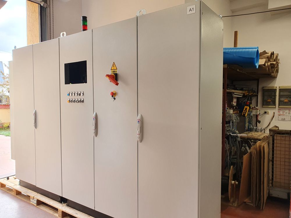
Case Study: Command and Automation Control Panel (Model: TEC 315kW/400V AC)
Client: HIDROELECTRICA
Project Specification: The primary function of the automation system is to maintain the water level within predefined limits in the pump’s suction line.
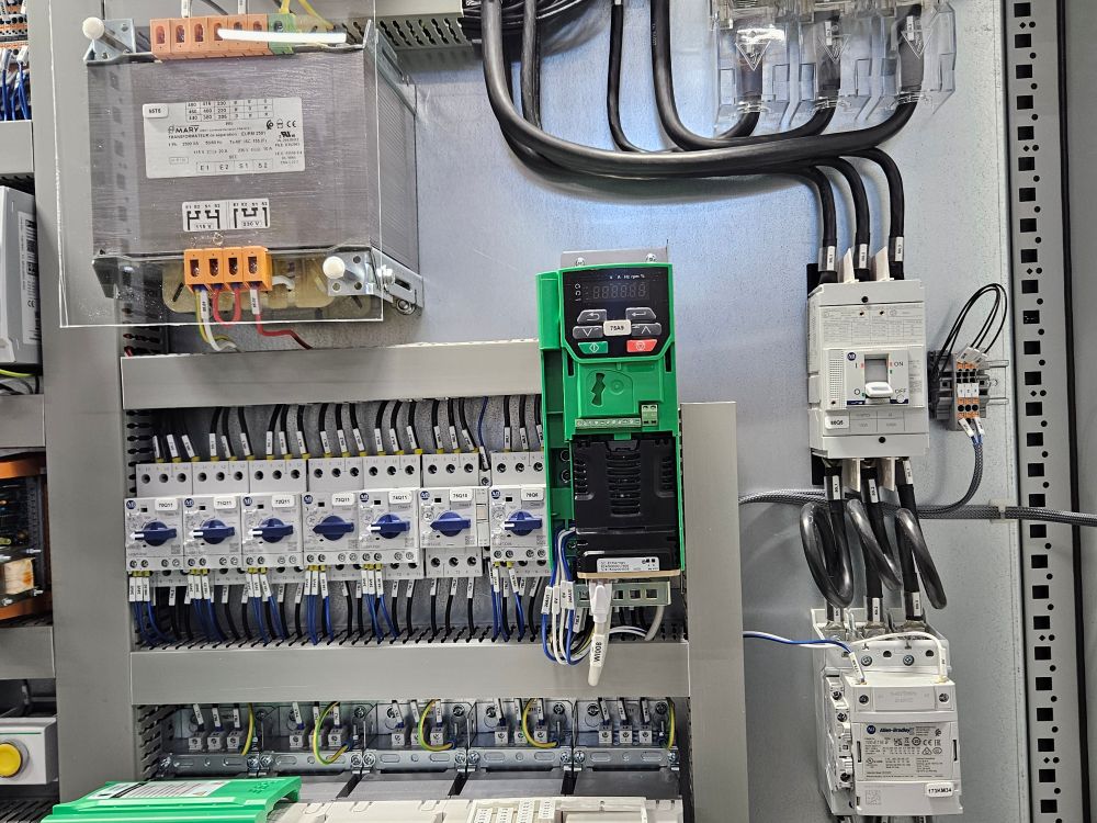
Case Study: VFD Control Panels for Pumping Systems
Project: Automation Control Panels with Variable Frequency Drives (VFDs) for 37kW and 110kW electric pumps.
Client: ROMAG-TERMO Drobeta Turnu Severin.
Key System Functions:
- Maintaining the level within the condenser at the prescribed setpoint.
- Providing a full interface to the Central Control Room (CCT in Romanian) for control, signaling, and monitoring functions.
- Enabling system operation in both automatic and manual modes.
- Continuous monitoring and diagnostics for the drive system and its associated transducer signal circuits.
- Ensuring maximum system safety and operational availability.
- Logging of operational hours, categorized by manual mode, automatic mode, and total runtime.
- Individual logging and tracking of all fault conditions that occur during operation.
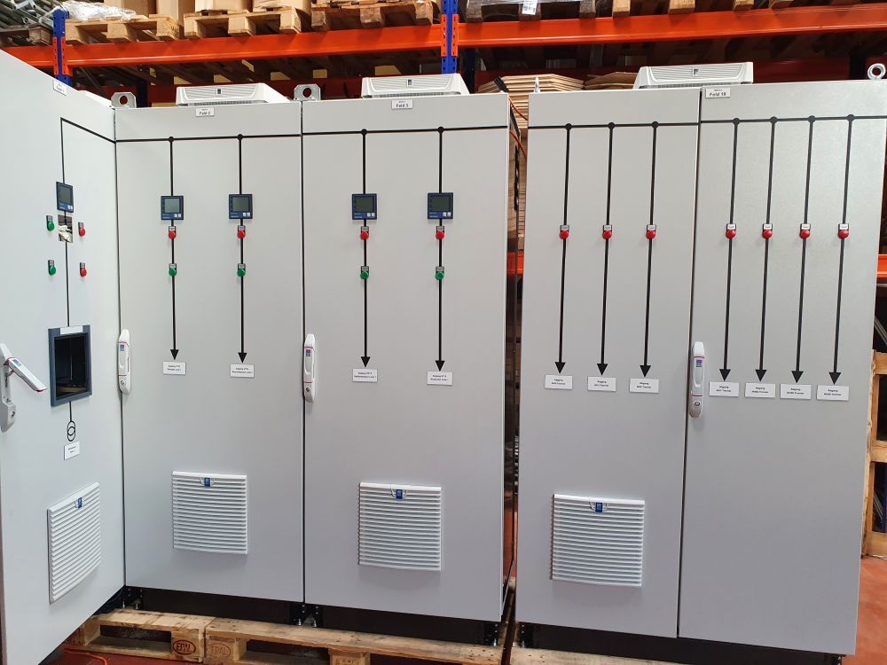
A medium voltage cell is an electrical switchgear unit designed for the primary or secondary distribution of medium voltage electrical energy in transformer stations, industrial substations, and other distribution points.
Application Areas:
- Thermal power plants
- Hydroelectric power plants
- Naval industry (shipbuilding)
- Petroleum industry
- Chemical industry
- Transformer stations and substations
These cells can be integrated into a remote SCADA monitoring system due to their high degree of automation. They can be outfitted with equipment from leading manufacturers such as ABB, SCHNEIDER, EATON, SIEMENS, or other producers, according to our clients’ specific requirements.
Case Study: Medium Voltage VFD Control Panel for Condensate Pumps
Project: Automation control panel featuring a 700kW / 6kV medium voltage Variable Frequency Drive (VFD) for primary condensate electric pumps.
Client: Turceni Energy Complex.
Functions of the Automation Panels:
- The VFDs supply power to the 700kW motors that drive the primary stage II condensate pumps (P46).
- The system must operate without introducing harmonic distortions or other disruptive factors that could negatively affect the lifespan of the motors.
- Upon power restoration after an Automatic Rapid Reclosing (ARR) event, the system must prevent motor insulation breakdown by avoiding out-of-phase energization against the residual voltage in the motor stator.
- The VFDs can be controlled via the existing Distributed Control System (DCS).
- The VFDs can be operated through an automatic regulation loop.
- The system ensures the specific automated functionality required for primary condensate lines.
- The system permits both local and remote command.
- In the event of analog signal loss, the VFD will hold the last valid value and signal the fault, continuing to operate based on that last command.
Motor Protection Systems
Our company produces a proprietary range of relays for motor protection, which includes: overload relays, level control relays, timing relays, and phase sequence relays.
Electronic Overload Relay – RE-SS
This relay provides complete protection for three-phase electric motors with power ratings between 0.37 kW and 90 kW. It protects the motor against:
- Overload conditions
- Locked Rotor
- Phase Loss
- Current Asymmetry
- Extended Start-up Time (exceeding the configured start time T(s))
Electronic Level Control Relay – RE-N-2
This relay protects submersible pumps from running dry and enables automatic start-up when a maximum water level is reached. It can also be used in water tank automation systems to provide signaling or command functions based on the water level.
Electronic Timing Relay – RE-T-1
This relay is used to provide the necessary time delay for the star-delta starting sequence of three-phase motors.
Electronic Phase Sequence Relay – RE-SF
This relay permits motor start-up only when the three phases are in the correct R, S, T sequence.
Electronic Lighting Control Relay – RE-CI
This device is intended for use in automatic lighting systems, such as street lighting, domestic applications, etc.
Phase Loss Detection Device – DDLF
This device is specifically designed for the protection of three-phase electric motors, regardless of their power rating, by continuously monitoring the voltage on all three phases.
Reference projects
Explore our work to see how we transformed complex challenges into engineering success.
Media gallery and examples